Comparison of Ventilation Concepts
Comparison of three ventilation concepts of a production hall with the help of mixed flow and particle simulation - from 3-D CAD models to a detailed evaluation:
The production hall is sized 10x10x3 meter. The ventilation system supplies maximum 2400 cbm/h fresh air. The following ventilation concepts were compared:
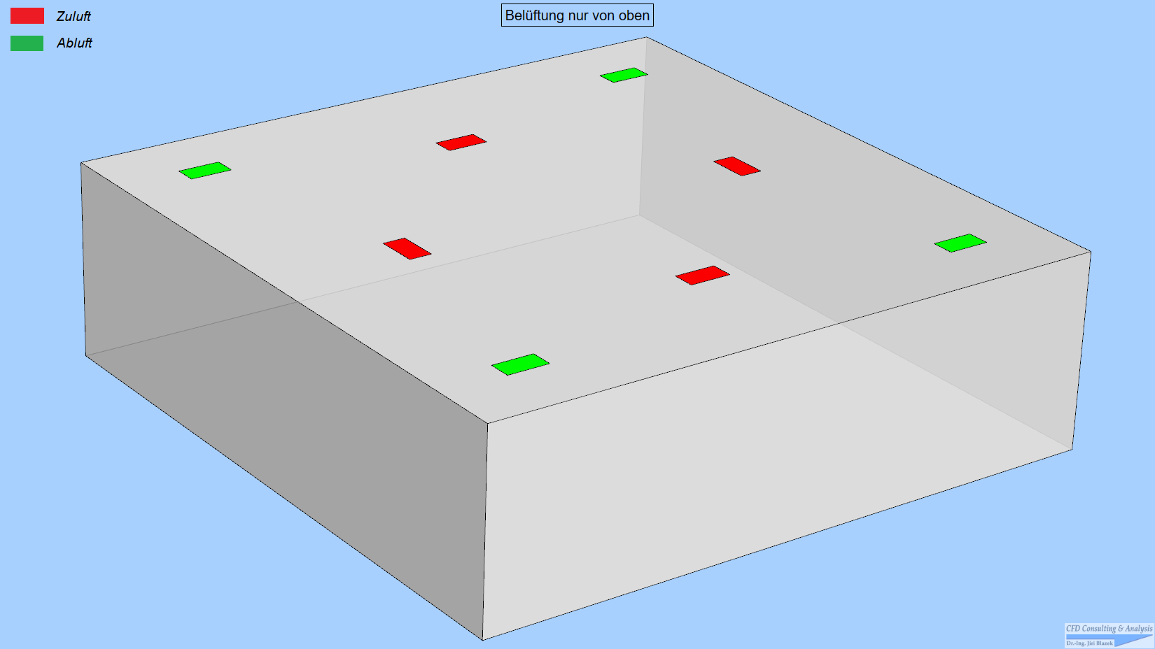
- All air entry and exit vents on the ceiling.
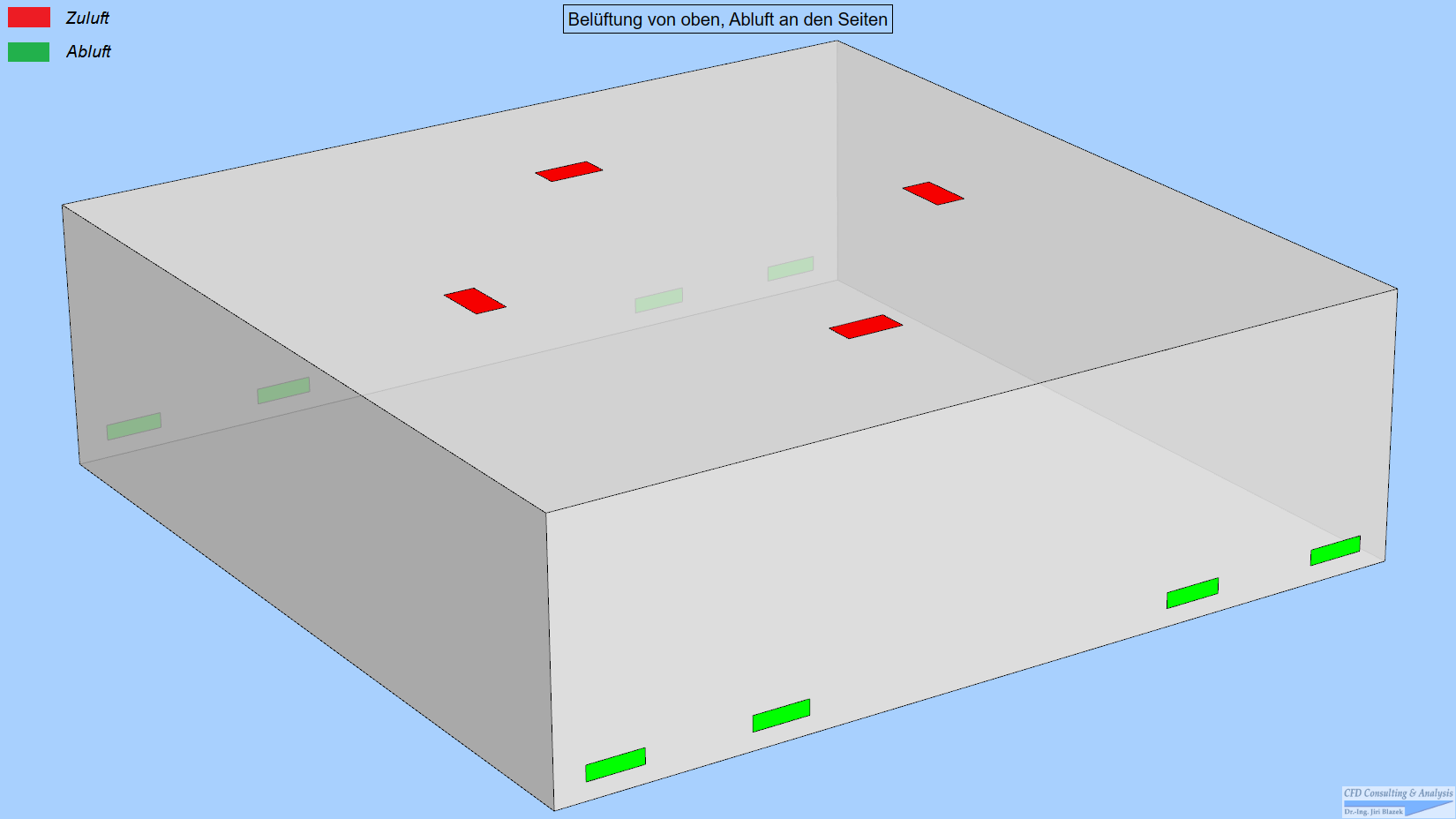
- Air entry vents on the ceiling, exit vents on the walls near the floor.
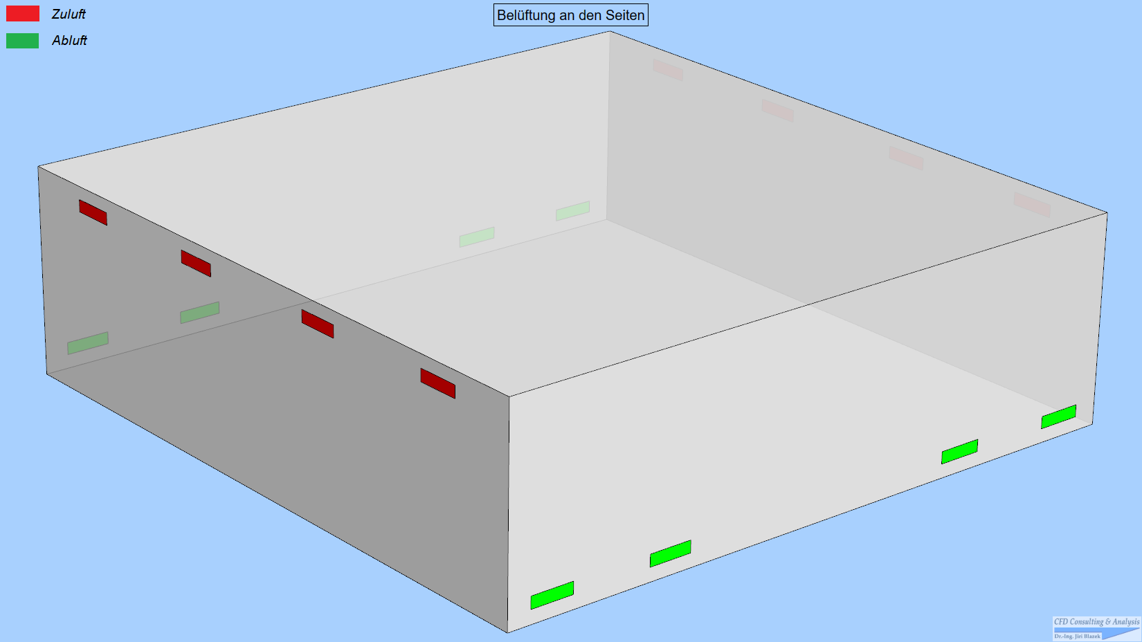
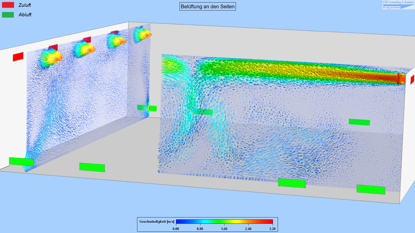
- Air entry vents on two walls, exit vents on the remaining walls near the floor.
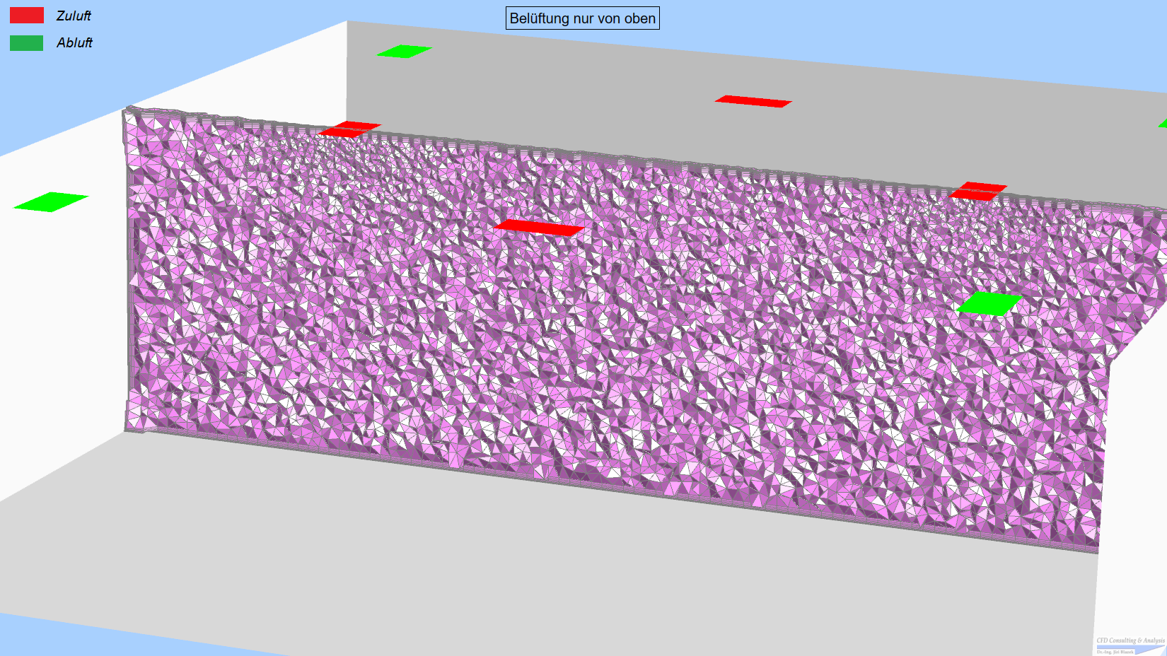
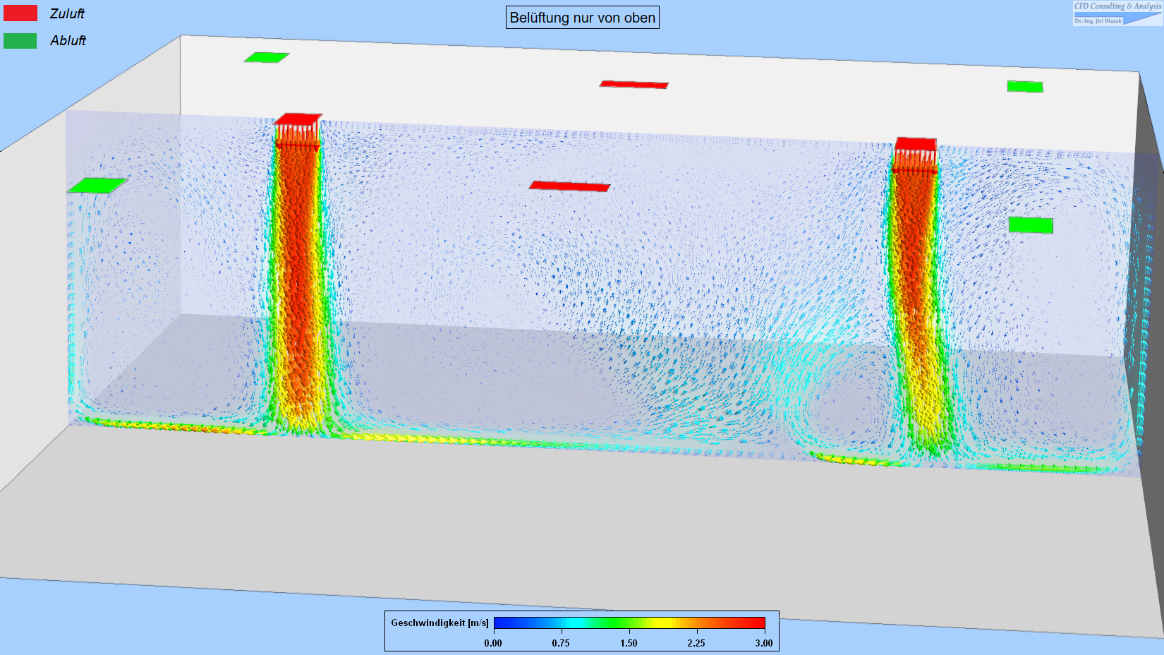
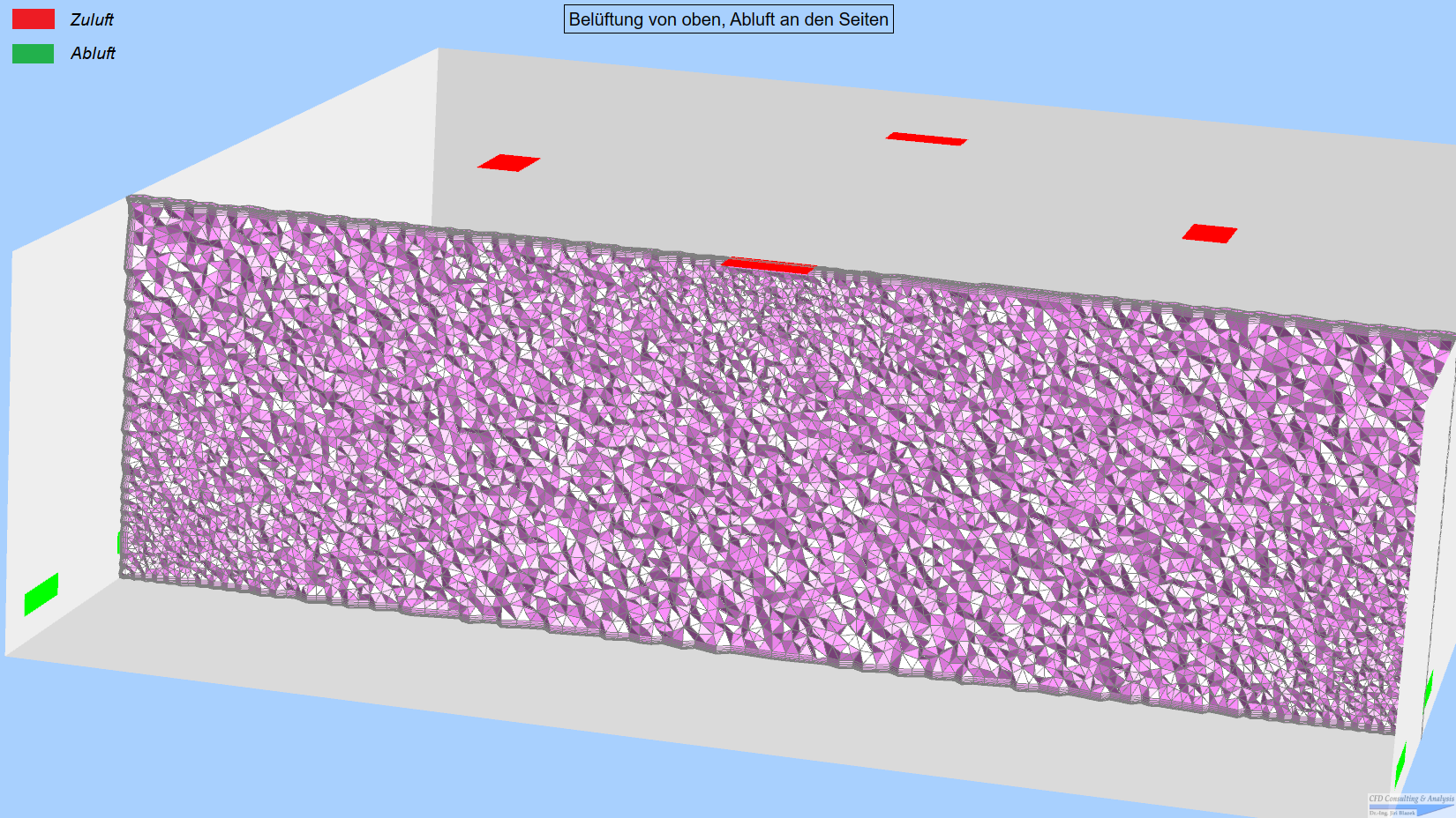
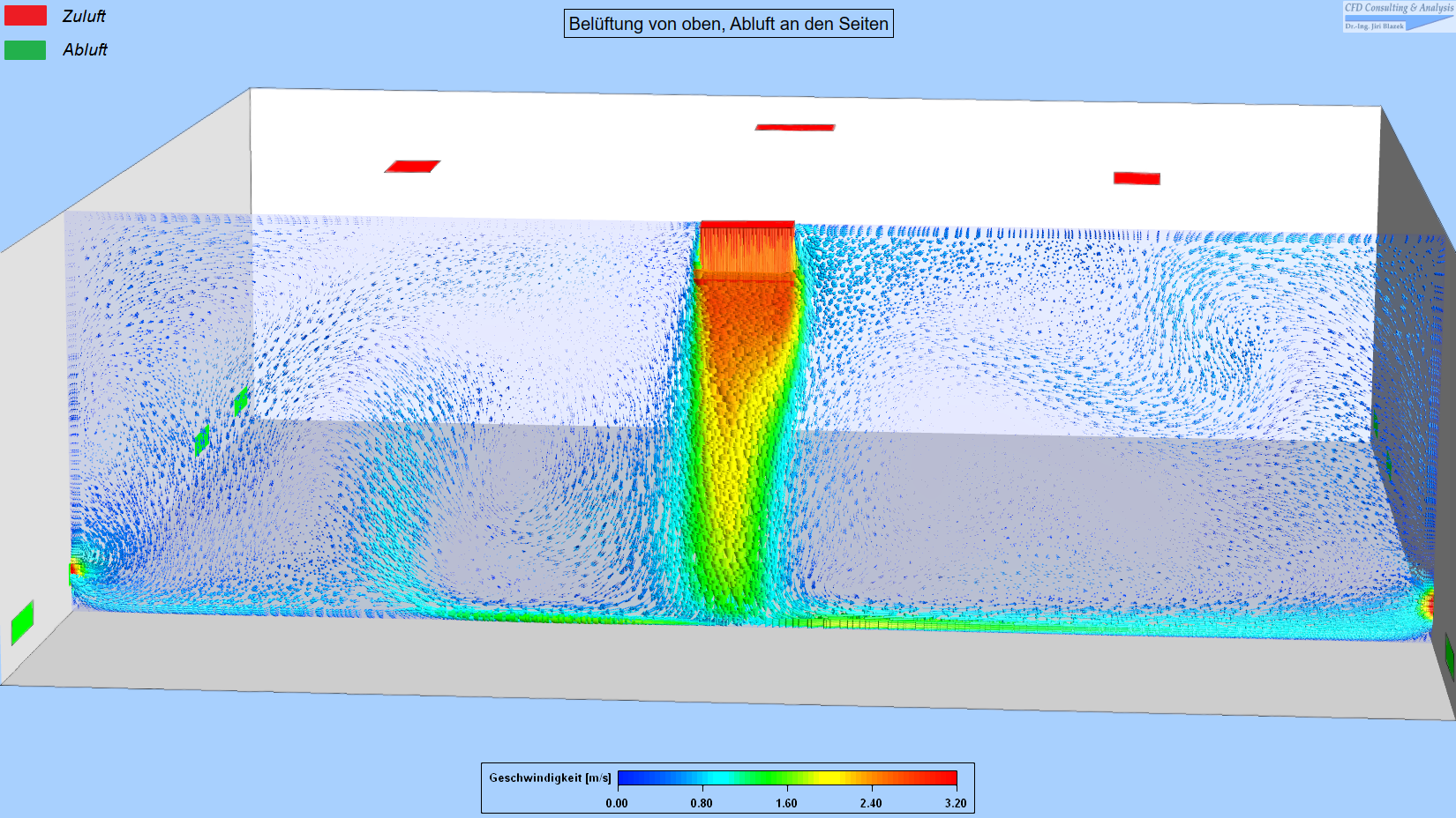
The following pictures are for the concept 1. They show the CAD model (entry vents colored red, exit vents green), a slice through the volume grid (consisting of about 4.8 million tetrahedral and prismatic cells), as well as a depiction of the unsteady flow vectors (colored by the velocity magnitude):
These pictures present the configuration and the flow solution for the second concept. In this case, the volume grid is composed of about 5.8 million tetrahedral, prismatic and pyramidal cells:
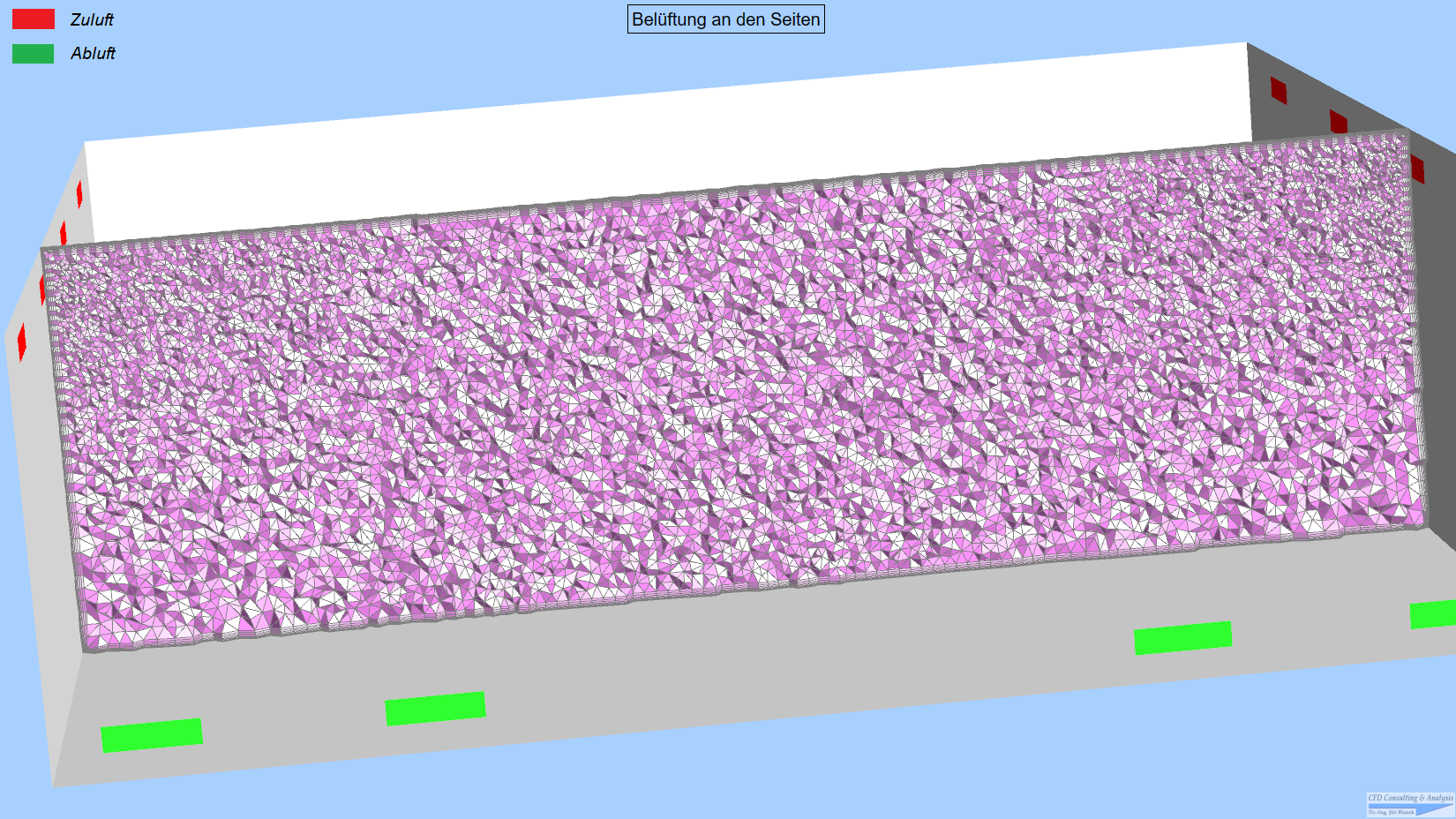
Finally, the following pictures show the respective depictions for the third concept. Because of the smaller areas of the entry and exit vents and hence a more refined elements there, the volume grid consists here of about 8.2 million tetrahedral, prismatic and pyramidal cells:
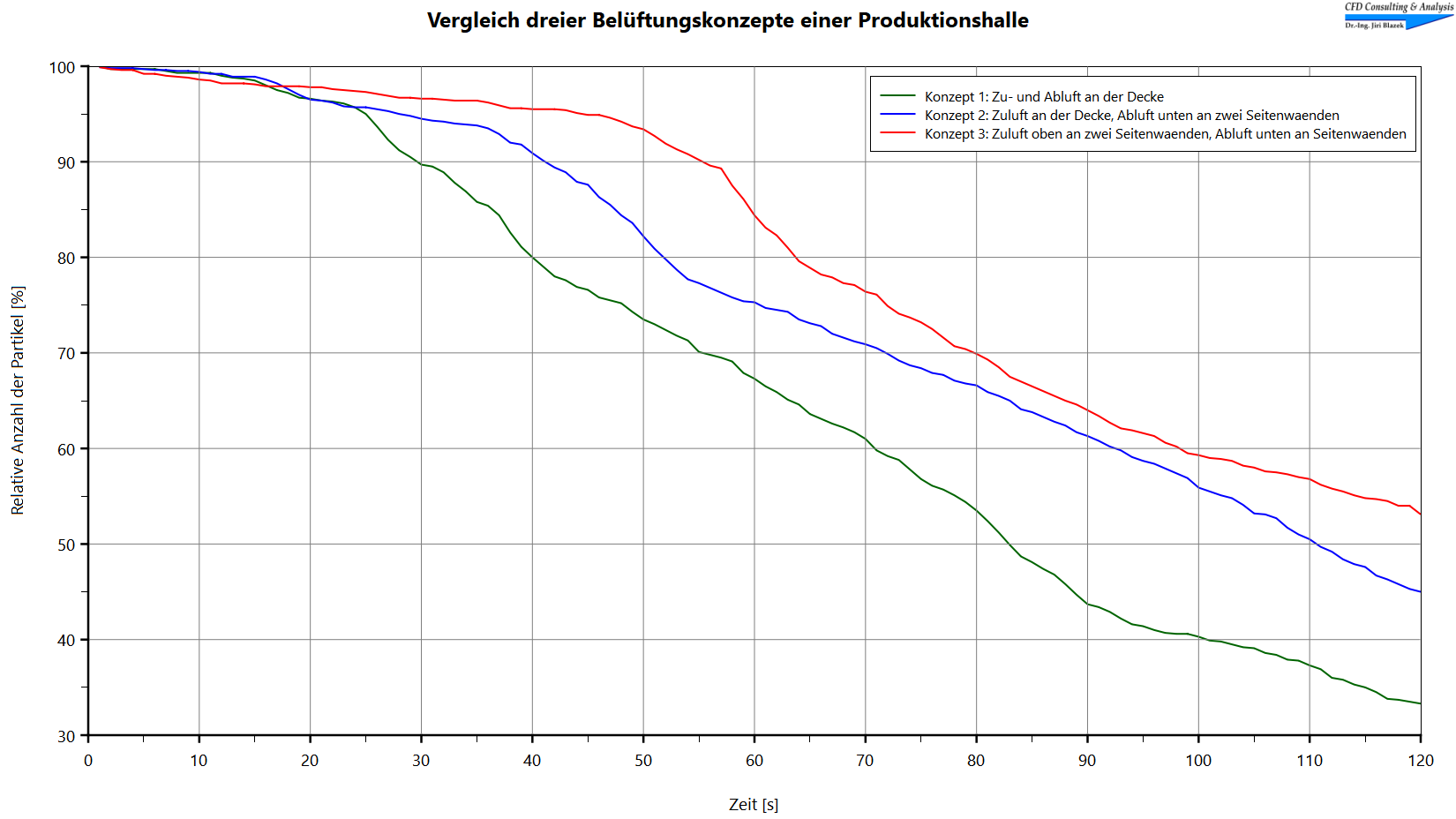
In order to compare the ventilation concepts to each other, we simulated the motion and mixing of a cloud of very fine particles. In all three cases, the particle cloud was initially placed at the center of the hall. The trajectories of the particles and their possible exit through the vents to the outside were monitored for 120 seconds. The changes over time of the relative numbers of the particles remaining inside the hall are compared in this diagram:
It is apparent that the 1st concept (all air entry and exit vents on the ceiling; green line) is the fastest in expelling the particles out of the production hall.
If you can imagine or actually plan to carry out similar flow / particle simulations, please do not hesitate to contact us.
© 2011-2026, CFD Consulting & Analysis. All rights reserved.
