Gridder: Generation of 2-D and 3-D Unstructured Grids
 This software enables you to generate two-dimensional and three-dimensional unstructured grids for CFD or FEM simulations. The grids may consist of various elements: triangles and quadrilaterals in 2D, tetrahedrons, prisms and pyramids in 3D. Gridder can import geometry data and export finished grids in various formats. Geometrical objects can also be defined or modified from within the software. All steps of the grid generation process are controlled by an intuitive graphical user interface. Gridder is a native Windows® program and runs on Win10 or Win11.
Main features:
- Import of geometry data in IGES format for a connection to virtually all CAD systems
- Tools to construct objects and boundaries of the simulation domain (guaranteed "watertight"):
- Lines, circular arcs and spline curves (either interpolating or approximating given points)
- Planar, revolved, ruled, lofted, and patched surfaces
- Transformation by translation, rotation, scaling and mirroring
- Various possibilities to correct, modify or to enhance any imported geometry
- Grid density controlled globally with the possibility to adjust point distribution on any curve segment
- All lines, arcs, curves and surfaces defined as NURBS (NonUniform Rational B-Spline) objects for a mathematically clean and versatile representation
- Option to compose the grid of a number of (possibly independently meshed) regions
- A selection of methods to generate 2-D and surface meshes with options to control the grid quality
- 3-D volume meshes generated by the Delaunay scheme (we plan to add the Advancing Front method in the future)
- Capability to generate viscous sub-layers using quadrilaterals in 2D and prisms in 3D
- Possibility to refine / coarsen the point distribution and optionally also all surface meshes and the volume grid
- Option to assign various types of boundary conditions to the boundaries (meshes are automatically updated on connected periodic boundaries)
- A choice of file formats to export the finished grid:
- CGNS (CFD General Notation System) format using either HDF5 (Hierarchical Data Format) or ADF (Advanced Data Format)
- GAMBIT neutral file format
- OpenFOAM format (open source CFD toolbox). During export, 2-D meshes are automatically extended to 3D as it is required by OpenFOAM
- SU2 format (freely available CFD solver)
- Unstr2D format (used by the free example CFD codes)
- Formats of our own flow solver and visualization tools
- Custom format (a plugin you can utilize for output in your own file format)
- Possibility to save and import data of curves and surfaces (useful to share geometry data between similar meshing projects)
- Option to save surface grids in STL (STereoLithography) format
The software package contains examples of various popular 2-D and 3-D CFD test cases. Furthermore, there is a MS VisualStudio® project with generic C++ code for the mentioned custom format plugin.
The current program version is 5.6 from 12/21/2025. For changes and bug fixes see the Release Notes.
A YouTube video on our channel shows how Gridder can be configured and used to generate 2-D unstructured mesh with viscous sublayers. One further YouTube video demonstrates the basic steps of 3-D grid generation process, starting with a CAD model through to the finished viscous mesh.
Licensing:
We offer Gridder for the Windows® platform (64-bit, 10 and higher) only. Two versions are available:
- Commercial one which requires you to purchase a license (please, contact us for an individual offer tailored to your setup); the license comes with e-mail support and updates
- Free version with limited maximum number of grid elements (32,000 in 2D and 750,000 in 3D) and no support; the installation executable can be downloaded here from our server.
Examples of Meshes Generated by Gridder
The following images show screenshots of Gridder while used to mesh various 2-D and 3-D geometries
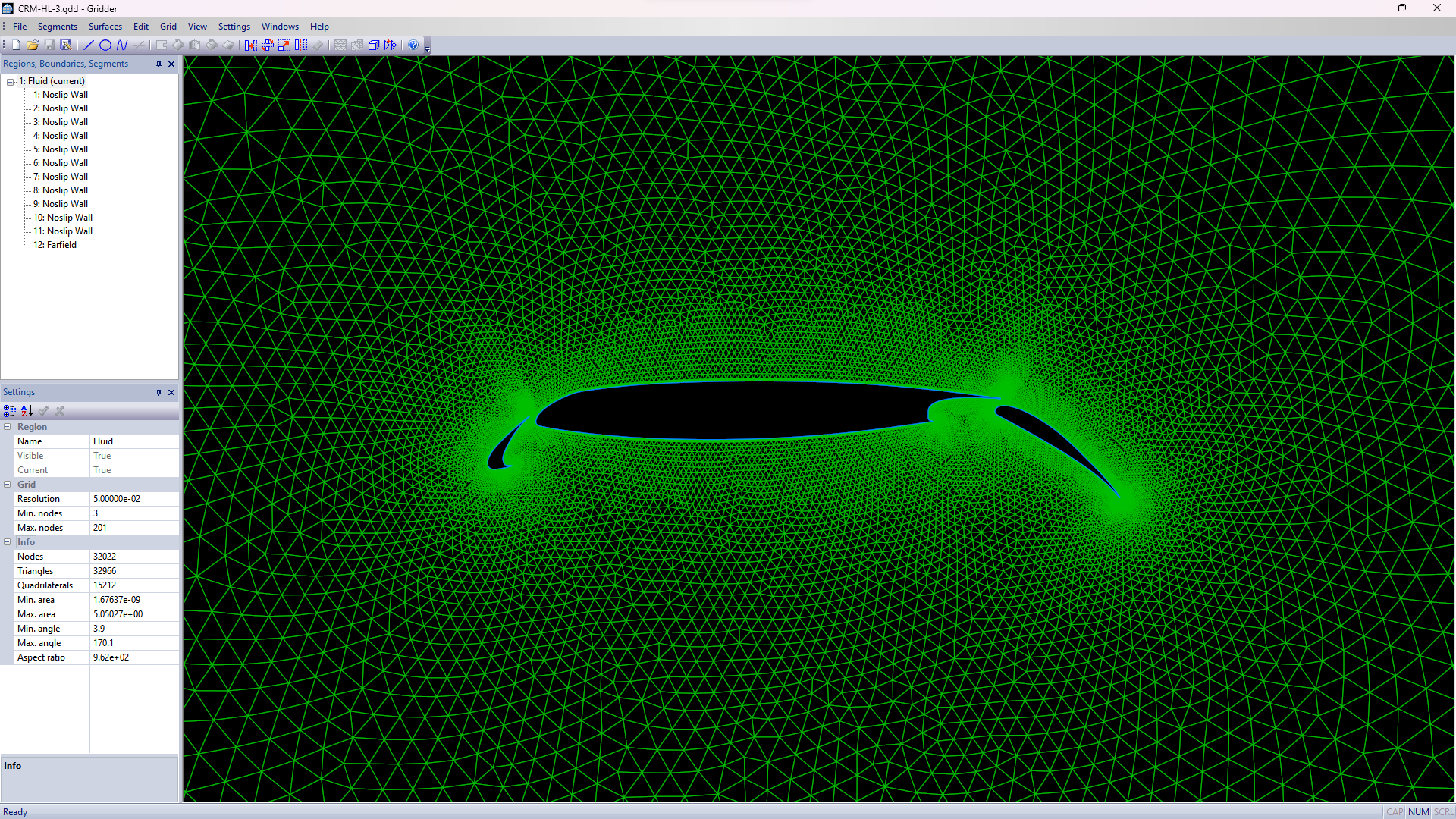
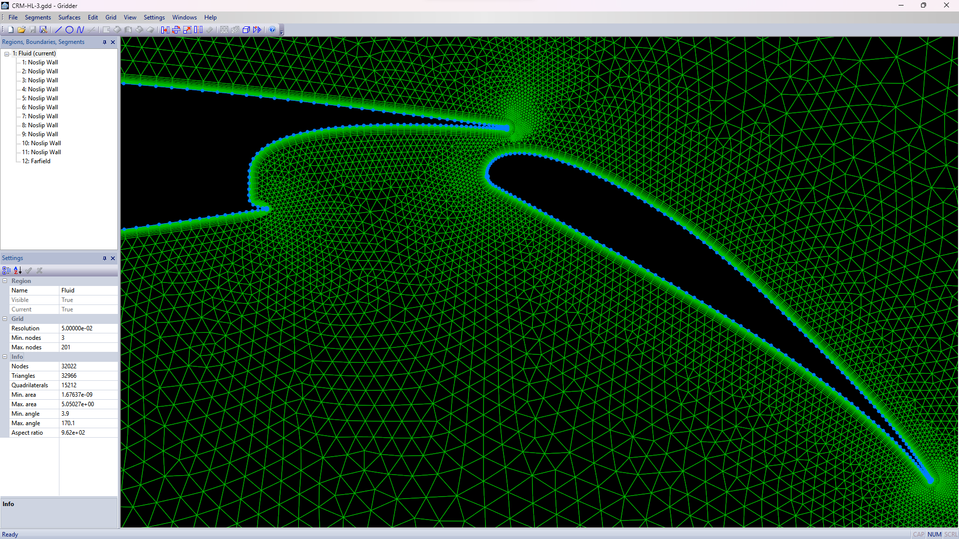
The above images (click to enlarge) show the NASA CRM-HL 3-element wing section. The grid consists of 15,212 quadrilaterals forming the viscous layer and of 32,966 triangles filling the rest of the domain (far-field is located 30 chords away). The triangular grid was generated by the Advancing Front Method and then smoothed using the spring analogy. Note the possibility to cluster grid points where deemed necessary, as well as the smoothly varying element sizes.
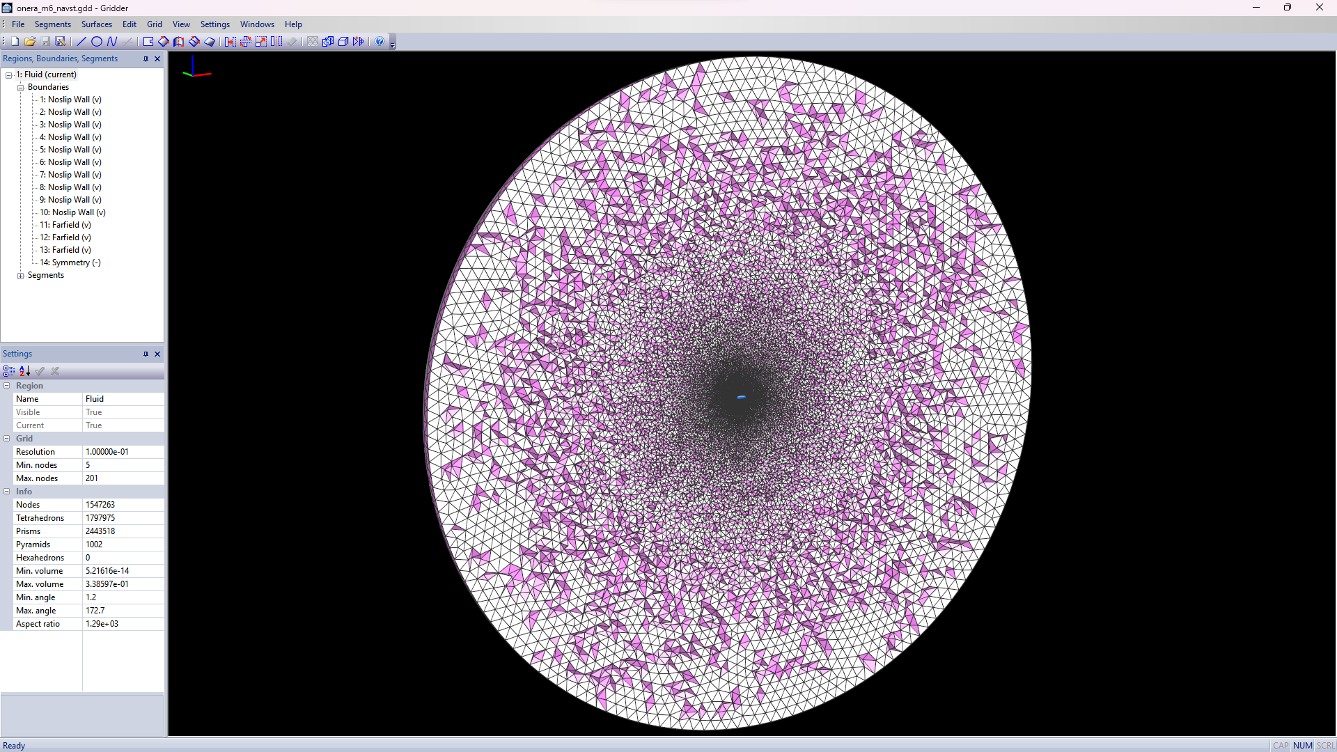
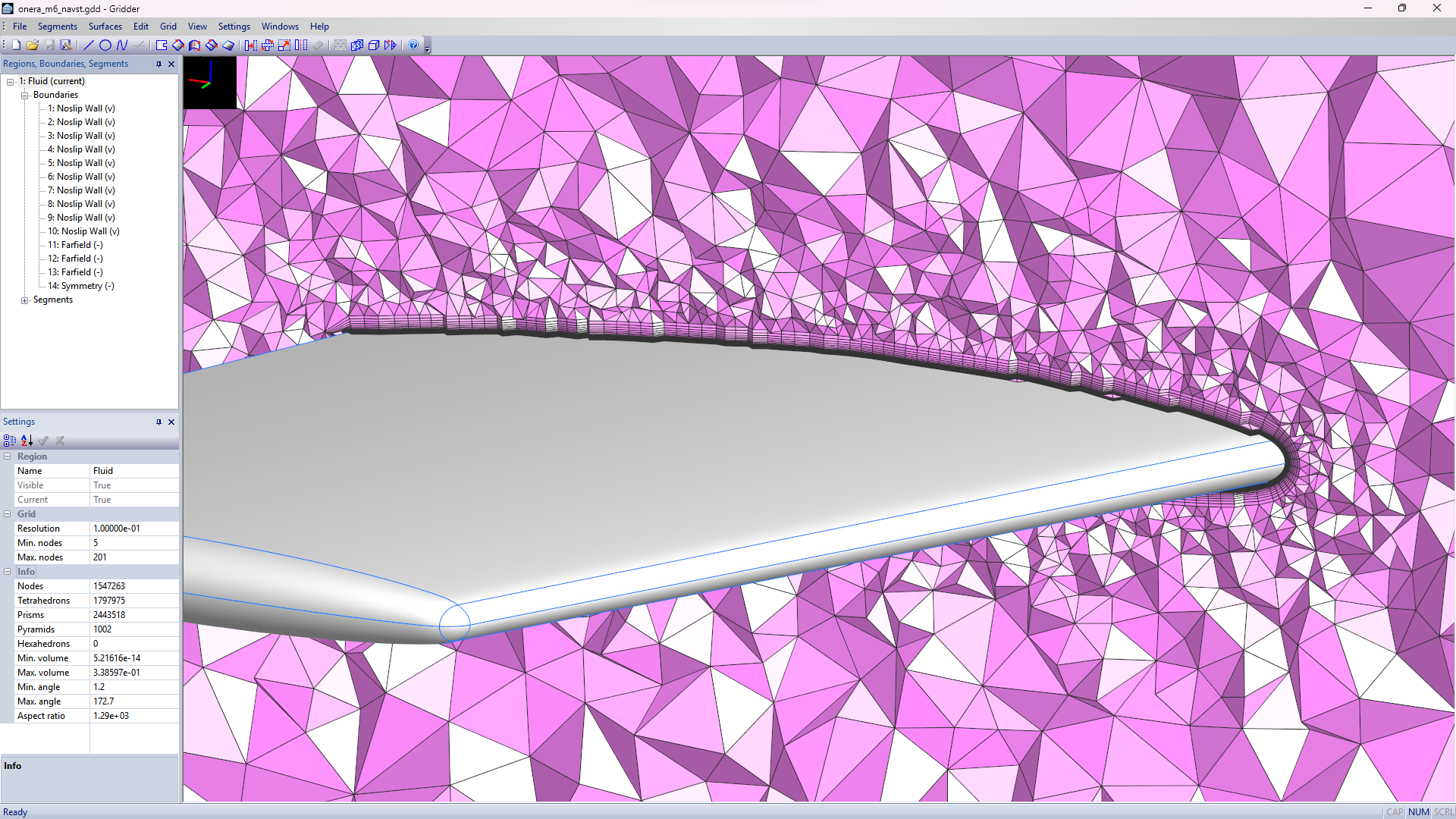
The above images (click to enlarge) display the Onera M6 wing, a popular test case for turbulent, transonic external flow. All surface patches, except for the symmetry plane, were imported from an IGES file. The symmetry plane was added in the form of planar surface, bounded by the airfoil contour and circular arcs at the far-field. The finished 3-D grid consists of 2,443,518 prisms forming the viscous layer enveloping the wing, of 1,002 pyramids as interface elements, and finally of 1,797,975 tetrahedrons filling the rest of the domain (far-field is located about 30 chords away). The tetrahedral grid was generated by the Delaunay scheme with optimizations of the grid quality. The image on the left side shows a rough cut through the complete flow domain. On the right side is a zoom of the cut displaying the viscous layers.
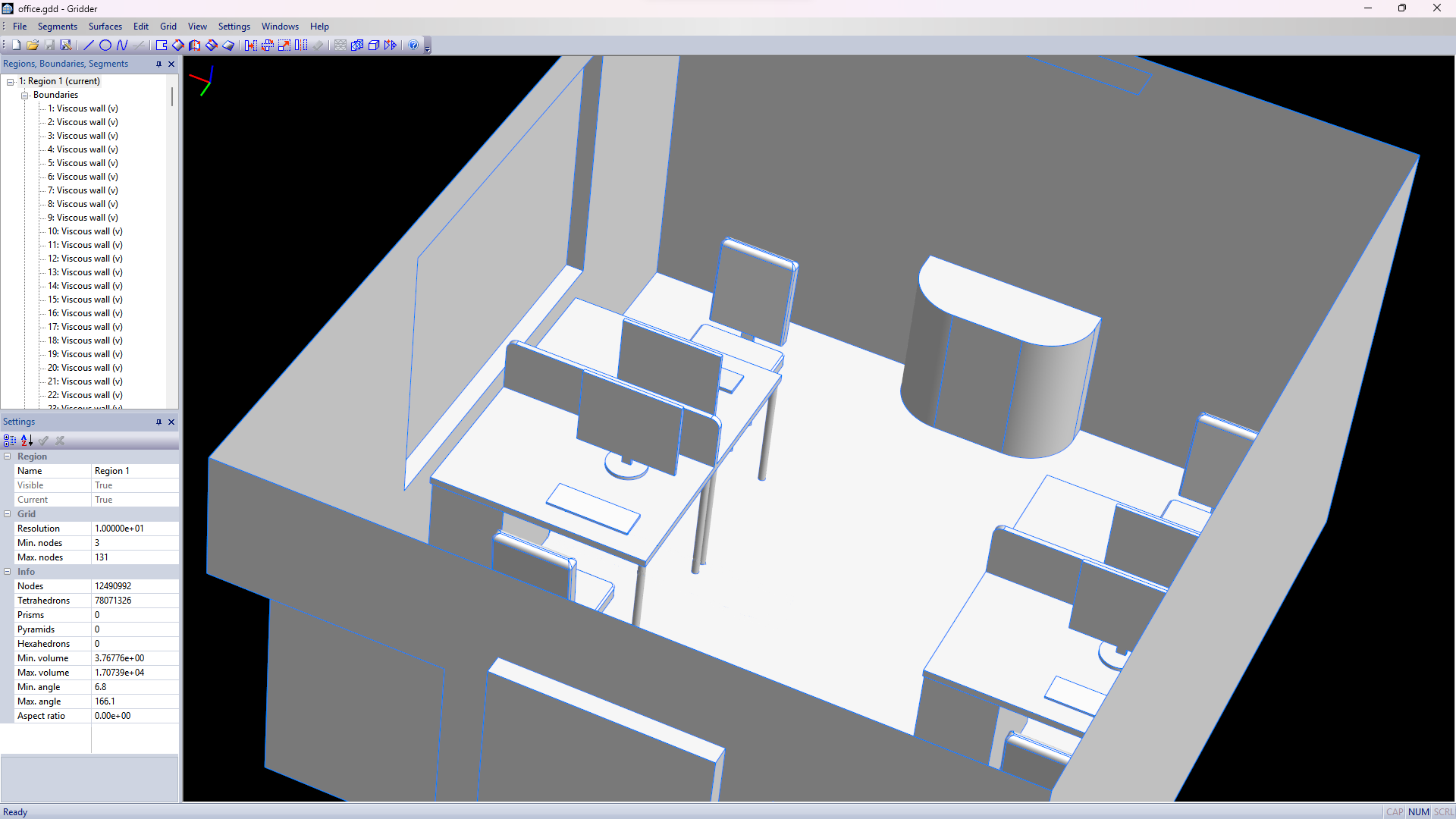
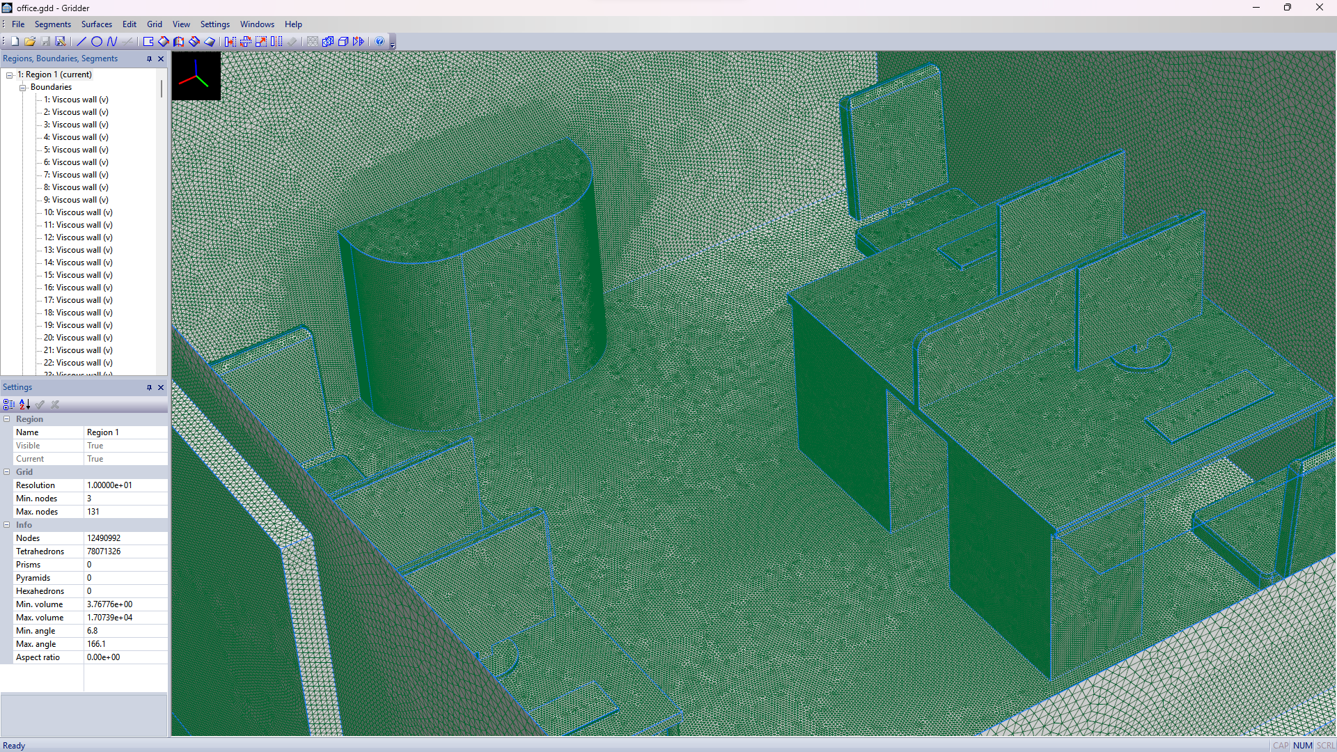
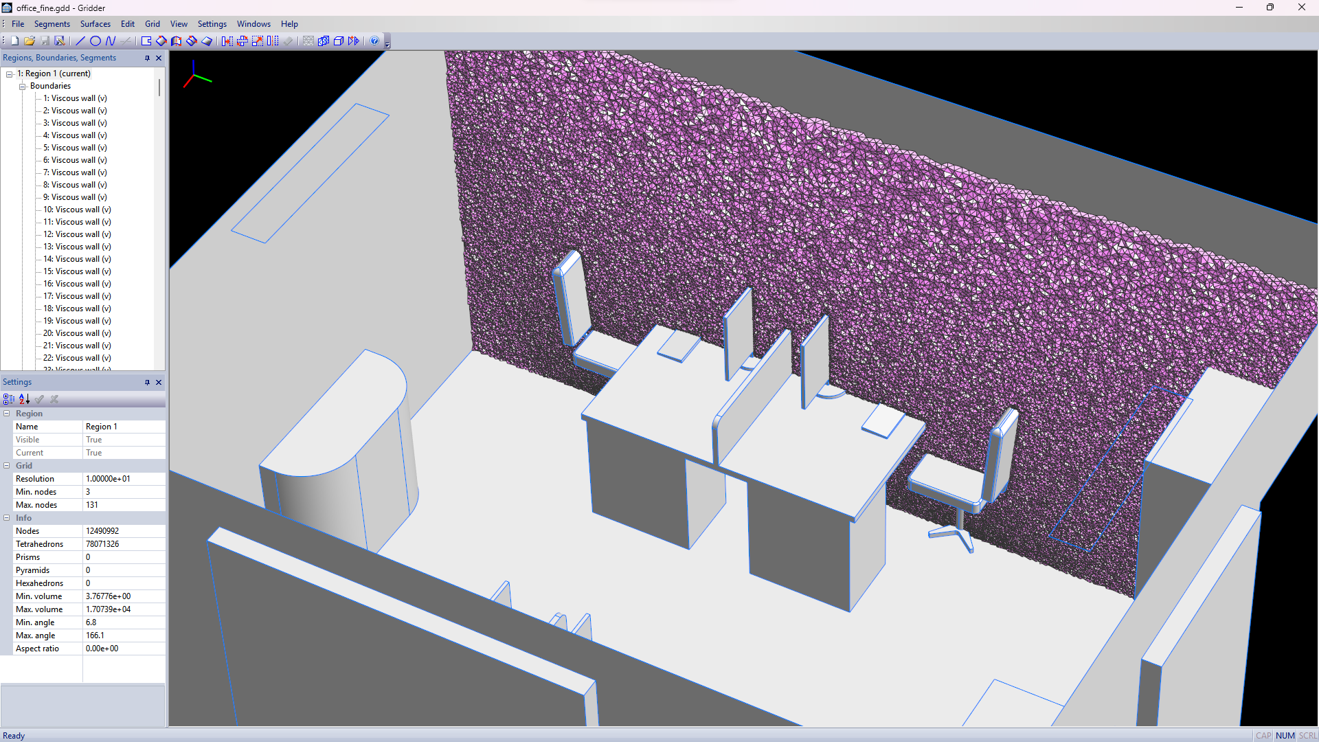
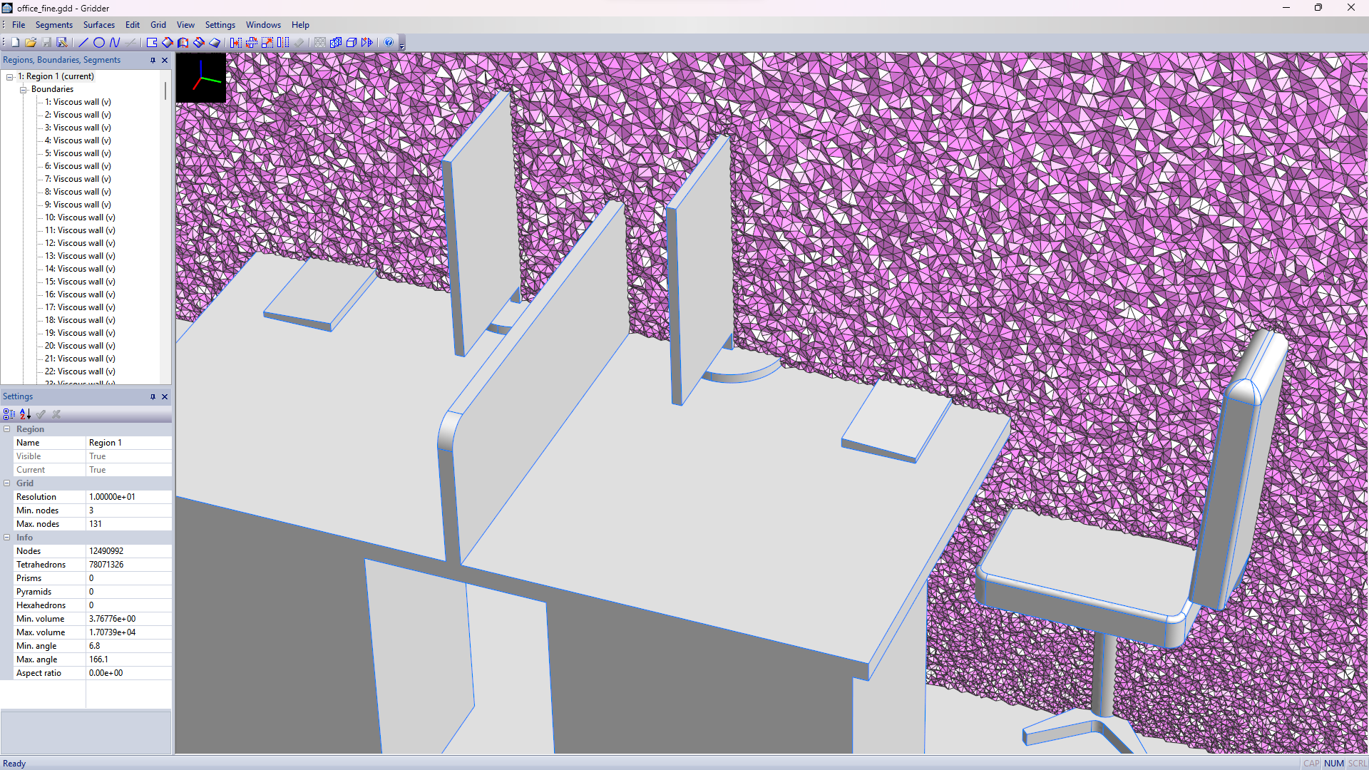
The above set of images (click to enlarge) shows an example of office ventilation (results of flow simulation on an initial coarser grid can be seen here). The surface patches were imported directly from CAD software in the form of an IGES file. All surface meshes were generated by the Advancing Front Method. The refined 3-D grid consists of 78,071,326 tetrahedrons and was generated by the Delaunay scheme with optimizations of grid quality. This is so far the largest mesh produced by Gridder. It took about an hour to generate (on Ryzen 9 series processor) and maximum 16 GBytes of main memory. Images in the top row display the surfaces (left) and the surface grids (right). Note the possibility to adjust sizes of the surface elements individually for each patch (and if needed for each curve). Images in the bottom row show a rough cut through the flow domain. Note the regularity of the tetrahedrons.
© 2011-2026, CFD Consulting & Analysis. All rights reserved.
